Designing parts for CNC machining is one of those skills that really combines creativity with technical knowledge. I’ve had the chance to work on dozens of CNC-machined parts, from simple brackets to complex mechanical assemblies.
And let me tell you, a well-designed part doesn’t just look good—it saves time, money, and stress once it hits the machine.
If you’re someone in the USA trying to understand how to get started or improve your CNC design game, you’re in the right place.
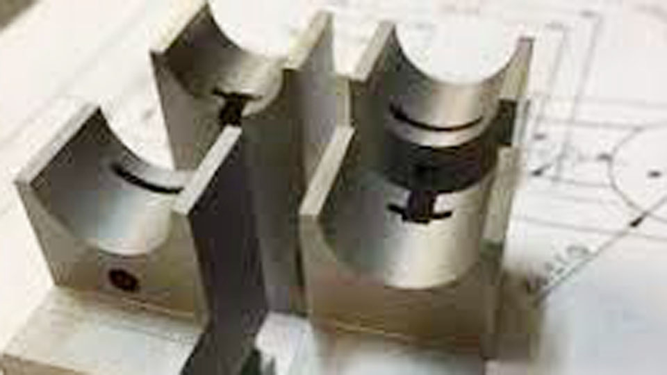
Photo by indiamart
I’ll share everything I’ve learned along the way—things that worked, mistakes I’ve made, and the small details that make a big difference.
If you’re a beginner trying to figure out how to avoid common pitfalls, or someone with a bit of experience trying to optimize your next design, this article will help guide you.
What Does CNC Machining Actually Involve?


Before designing anything, it helps to know what CNC machining is all about. CNC stands for Computer Numerical Control. It’s basically the process of using computers to control machine tools like mills, lathes, and routers. With CNC, you can make parts with high precision, tight tolerances, and repeatable accuracy.
You start with a solid block or bar of material and then remove material using tools controlled by a program. This process is called subtractive manufacturing. And that simple idea of “removing material” affects how you design.
Every pocket, curve, and hole in your design has to be machinable with tools that spin, drill, or mill. It’s not magic—it’s physics, mechanics, and smart programming.
Understand the Basics of CNC Design
The first step to designing for CNC is to keep things simple. The more complex a part is, the more time it takes to machine—and the more it can cost.
Here are a few basic principles I always follow:
- Use standard tool sizes
- Avoid overly deep pockets
- Try to maintain consistent wall thickness
- Design with the right tolerances in mind
- Consider tool access and orientation
These may seem simple, but when you apply them consistently, it really makes a difference in the final result.
Material Choice Matters
Different materials behave differently during machining. Some materials are soft and easy to cut, like aluminum. Others like stainless steel or titanium are tough, which means longer machining times and more wear on tools.
Here’s a quick table that shows some commonly used materials and how they perform during CNC machining:
| Material | Machinability | Common Uses | Notes |
|---|---|---|---|
| Aluminum | Excellent | Aerospace, automotive, general parts | Easy to cut, lightweight |
| Steel (mild) | Good | Structural parts, gears | Strong, more tool wear |
| Stainless Steel | Fair | Medical, food industry, marine | Corrosion resistant, harder to machine |
| Brass | Excellent | Valves, fittings, decorative parts | Great surface finish, low friction |
| Titanium | Fair | Aerospace, high-performance parts | Very strong, hard to machine |
| Plastic (Delrin, Nylon) | Good | Bushings, insulators, housings | Easy to machine, but needs low speeds |
Choosing the right material from the start can save a lot of time later.
Design with Tool Geometry in Mind
One thing that might not be obvious at first is that CNC tools are round. Most milling cutters are cylindrical, so they leave rounded inside corners.
If your part has sharp inside corners, the tool simply can’t create them—at least not without extra effort or using specialized tools.
I usually design inside corners with a radius that matches a common end mill size. A good rule of thumb is to make the radius at least 1.5 times the tool radius. For example, if the shop uses a 0.25-inch end mill, design the corner radius as 0.375 inches or larger.
This small tweak can make your part much easier (and cheaper) to machine.
Keep Pocket Depths Reasonable
Deep pockets look cool in 3D models, but they’re a headache in real life. Why? Because removing lots of material means more passes, longer machining time, and increased risk of tool chatter or deflection.
I try to keep the depth-to-width ratio of pockets below 3:1. So if you have a pocket that’s 1 inch wide, try not to make it deeper than 3 inches. In most cases, shallower is better. You can always step down in multiple layers, but it adds machining time.
If I absolutely need a deep pocket, I plan it in a way that makes it easy to access with longer tools—or I break the part into multiple pieces and assemble them later.
Make Your Walls Sturdy
Thin walls are another common mistake. While it might look lightweight or efficient in CAD, thin walls tend to flex when the tool touches them. That leads to poor surface finish and sometimes ruined parts.
For metals, I try to keep wall thickness no less than 0.040 to 0.060 inches. For plastics, I go even thicker. If I need very thin sections, I make sure they’re short and well-supported.
Another good trick is to add ribs or gussets where possible. That gives the part more rigidity and keeps it from vibrating during machining.
Add Chamfers and Fillets Where Needed
Adding chamfers or fillets isn’t just about appearance—it also helps with function. Chamfers make sharp edges safe to handle. Fillets reduce stress concentrations and help with fatigue life.
Most CNC machines can handle chamfers easily with a 45-degree tool. For fillets, I usually match the tool radius as mentioned earlier. Adding these features also helps with part alignment during assembly.
Think About Setup and Fixturing
This is something I really learned by working with machinists directly. A beautiful design on the screen can be a nightmare to fixture on the table. CNC machines need to hold your part steady during cutting. If your design has odd shapes or doesn’t allow a flat base for clamping, it can be tricky to set up.
Whenever I can, I design my parts to sit flat on a table with minimal setup changes. Features like locating holes, flat faces, or even temporary tabs can help during machining and assembly.
Also, think about how many setups are needed. If your part requires flipping or rotating several times, it adds cost and complexity. A good design minimizes those transitions.
Use Tolerances Wisely
Here’s one that often gets overlooked. Not everything needs to be machined to 0.001 inches. Tighter tolerances increase machine time and cost.
Unless the part function really depends on it, I use general tolerances like ±0.005 inches. I only specify tighter tolerances where needed—for example, holes for press fits or sliding shafts.
If you’re not sure what tolerance to use, ask your machinist or refer to the capabilities of the shop. Most CNC shops can tell you what they prefer.
Design for Standard Tools and Sizes
Using standard tool sizes helps in two ways. First, it ensures the shop has the tool on hand. Second, it makes the program simpler and machining faster.
For holes, I stick to standard drill sizes like 0.125, 0.250, or 0.500 inches. For threads, I use UNC/UNF or metric threads based on what’s common in the USA.
Here’s a quick reference of standard drill sizes I often use:
| Hole Type | Size (inches) | Notes |
|---|---|---|
| Small hole | 0.125 | Good for pilot holes |
| Medium hole | 0.250 | Common for fasteners |
| Large hole | 0.500 | Used in brackets, mounting |
| Tapped hole | 0.201 | Good for #10-32 UNC threads |
Break Complex Parts into Assemblies
If your part looks like a puzzle, it might be better to split it into separate parts and assemble them. I do this a lot when dealing with undercuts or tight internal geometry. Splitting parts can allow easier machining and make replacements simpler later on.
Make sure to add features like alignment pins or tabs so the assembly goes together smoothly. I also like to plan for welding, bolting, or press-fitting if the design allows it.
Test Prototypes Before Final Production
Once I have a design I feel confident in, I usually start with a prototype. Even if the drawing looks perfect, holding a part in your hand gives you a different perspective.
A prototype helps you catch errors, test fit with mating parts, and evaluate tolerances. It’s also a great time to talk with your machinist and ask for feedback. Small changes here can save a lot on a large production run.
Use 3D CAD Models and Provide 2D Drawings
Most shops today prefer 3D models for programming, but don’t forget the importance of 2D drawings. I always provide both.
The 3D model gives them shape and volume, and the 2D drawing calls out tolerances, threads, finishes, and material specs.
I keep my drawings clean and easy to read. No clutter, no guesswork. The clearer the communication, the better the part turns out.
Surface Finishes and Post-Processing
If you want a smooth finish or need anodizing, plating, or coating—make sure to mention that early. Different surface finishes require different preparation.
I usually include a note on the drawing like “anodize black, Class 2, after machining” or “machine all surfaces to 63 Ra.” Surface roughness affects how the part feels and fits, so don’t leave it to chance.
Conclusion
Designing parts for CNC machining is more than just pushing buttons in CAD. It’s about understanding how machines think. It’s about choosing the right tools, materials, and strategies to create parts that are efficient to produce and function exactly as intended.
Once I started thinking like a machinist, not just a designer, my parts got better. They were faster to produce, more affordable, and more reliable. Every successful CNC project I’ve worked on had one thing in common—smart design from the start.
Frequently Asked Questions
What is the best material for CNC machining?
Aluminum is often the best all-around material for CNC machining. It’s easy to cut, widely available, and provides a great balance of strength and weight.
Can I design sharp inside corners in CNC?
Not really. Because CNC tools are round, they can’t create sharp inside corners. Always add a radius that matches or exceeds the tool size.
How tight should my tolerances be?
Use tighter tolerances only where necessary. For general use, ±0.005 inches is often fine. Tighter tolerances increase machining cost.
Do I need both 2D and 3D files?
Yes. 3D models help with toolpath programming, while 2D drawings communicate important details like tolerances, threads, and notes.
How do I reduce CNC machining costs?
Keep your design simple, use standard tools, avoid deep pockets, minimize setups, and choose machinable materials.
Can I use threads in my design?
Absolutely. Just make sure to specify the correct size and depth. Avoid threading very thin walls or very deep holes.
If you’ve got more questions about CNC part design, I’m always happy to help. Designing better parts is a journey, and the more you understand about machining, the smoother that journey becomes.